One of the most difficult things to design and build on a car is the steering mechanism. The steering mechanism is used to turn the car around the bends in the track. There are many different ways in which this can be done. In this topic I will explain two mechanisms; firstly I will explain a mechanism that is simplest, it's flaws and move to second mechanism, that is little bit complicated.
Steering is like a mind of car; it just obeys orders given by it and moves in that direction. In case of RC cars it is a most completed part. So an ideal steering must show following properties for RC cars.
- It must be moderately smooth; otherwise you cannot control it in proper way.
- The servo motor is used to control steering system, so you must properly insure front wheels otherwise it may destroy motor in case of bumps or crashes. Or steering system must have a mechanism known as servo saver.
Servo saver is a small spring mechanism that is used to absorb shocks that are produced by front wheels in case of crashers and insures servo motor. You can devise your own mechanism and since this is an integral part of steering mechanism or just put original one, that is obtained with car. Following is a picture of servo saver that is fabricated by us as shown in red circle.


Before we begin our first implementation we studied a case study of Ackermann steering mechanism in detail.
The details of the study
Pitman arm

It is shown by red arrow in above figure. The Pitman arm is used to connect the steering column to the tie rods. The arm changes the rotational (turning) movement of the steering column to a sideways motion in the tie rods.The tie rods are connected to the steering arms, which then change the sideways motion back into a rotational movement, which turns the wheels.
By changing the length of the Pitman arm we can change the amount the wheels turn. The steering arms are connected to the wheels using a stub axle, and a pivot point called a king pin as show by blue colored arrow. These linkages show how the car driver can make the wheels turn from turning the steering wheel, but by how much should we turn them to get round a corner?
Turning angle
Above question can be answered here. We may think at first that both front wheels of the car have to turn to the same angle to get round a bend, but that is not correct.If a car goes around a circle or bend, the outside wheels have to travel further than the inside wheels .To make the wheels go round these different distances they need to turn by different amounts.
Suppose we draw an angle between the rear axle of the car, the centre of the circle and the centre of each front wheel, we see that this angle is different for each wheel. Using trigonometry, we can see that these angles are also the angles by which each wheel needs to turn into the curve. The inner wheel always turns more than the outer wheel; the difference between these two angles (Θ1 minus Θ2) is called the 'toe-in' of the wheels.

Fig: 2
For example, if the inner wheel turned by Θ1 = 45°, and we assume the car dimensions to be x = 1m and y = 2m, then;
- r = y/tan (Θ1) = 2/tan(45°) = 2/1 = 2m
- tan (Θ2) = y/(x+r) = 2/3, so Θ2 = 33.6°
- Toe-out = Θ1 - Θ2 = 11.4°
So how do we get the two front wheels to turn by different amounts? The idea is to angle the steering arms of the steering linkage towards the centre of the car so that the tie rods change the wheel angles by different amounts.
Calculating of the exact angle of each steering arm is complicated but angling the steering arms so that a line drawn from the centre of each arm meets at the centre of the rear axle gives a good result.As shown in figure 3.

Fig: 3
Conclusions
Using a design with four wheels at each corner makes the car more stable but makes the steering more complicated.The front wheels should turn at different angles to get around a bend. This can be achieved by using Ackermann steering i.e. angling the steering arms towards the centre of the rear axle.
Our implementation
After the complete analysis of the Ackermann steering mechanism, we developed steering mechanism for our car. The system is not much complicated, it is a simple mechanism. The turning angles, tow- in, tow -out are calculated and adjusted according to the formulations taken from the case study. From above case study we just concluded a point i.e. during a particular bent the outer wheel must bend lesser than inner by an amount, so that it can produce lesser friction and car can move smoothly.
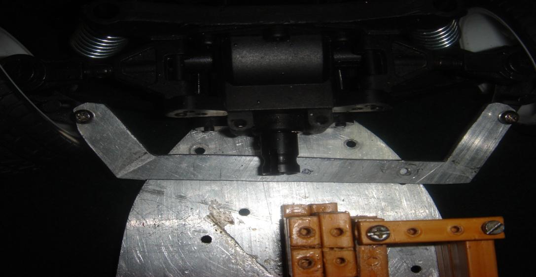
As our first race organizers did not accept more from us regarding steering. So we just cut a metal sheet that is a residue of plate left after complete fabrication of chassis and it provides needed steering effect. That plate structure is show below.

Fig: 4
The upper 2 holes are used to connect the metal part to the wheel hubs in order to produce movement that tends to produce the steering effect. The lower hole is used to connect servo limb to it. Below figure shows actual placement of plate in order to compete our steering mechanism. However this is our first implementation and here we did not used any ball joints, pipes etc. It is just crude implementation.

Fig: 5
Below are actual pictures taken from our car that clears actual shape and location in steering system. So when ever servo motor moves in the direction as shown by blue colour line in below photograph it leads to the left and right movements.

Position in straight direction.

Position in Right direction.
In following photograph I showed the spoke that joins servo horn to the metal plate. The spoke is pointed by red colored arrow. Don’t go for any specific rod because bicycle spokes are best suited.

Initially it appears to be a good design and worked in desired manner. But soon we paid a heavy price for above implementation. During a practice cession car bumped a wall that results in a damage of servo motor because our front wheels are not properly insured against such bumps. As I stated earlier we bought it from USA for price of around INR 900. If you are using above mechanism, it works fine but make sure, that you insured your car front wheels properly. If you do so I assure, it will work finely without any problem.
Failure of our first implementation forced us to change steering mechanism. This time we just took original parts of car that we bought from a Mumbai based vendor. And made those replicas by means of molten metal casting, we used brass metal for this purpose. And new design posed new challenges, such as finishing of parts and making holes at proper position as per our experience, this one is really headache work and forced us to make same parts again and again. Finally we succeeded in doing, following photograph shows our new steering mechanism as indicated by blue colored arrows. This worked fine without any insurance to front wheels and saved our servo motor several times.


This is a position when it took right turn.


Our steering mechanism contains ball, a joint that is capable of moving in all four directions. We participated in 5 races and as per my knowledge no one fabricated ball joints. But we succeeded in doing so without any too much cost and done it by using simple tool such screw driver. And below is typical ball joint photograph.

Initially we measured exact needed length and cut a metal plate in a shape as shown below.

As per our design drilled on proper positions to make holes, and made counters on only one side of holes. Took two plates and put a ball head screw. Sandwiched those plate by using glue known as Araldite (after putting screw head in between them) only after making sure that there is a necessary room for ball head to move freely. You can see below photograph to get its clear idea and it’s a cake walk. Once again I would like to say that this is just a one concept and you can use your own ideas to create a ball joint.


Finally we reached end part of this topic and I would like to give some advice, if you are an amateur then go for first implementation and provide proper guard to front wheels, or you already participated in few races and know more about RC cars then go for second step because as per our views, we faced a lot of problems while fabrication, particularly while putting holes at proper positions.
And this concludes steering topic and best of luck for your future races. If you are still facing problems then don’t hesitate to mail me at bpr890@gmail.com.
Thanks and Regards.